yeold

A blog about my projects and whatnot

The Flipper Zero with the Nibble Zero on top

The node that integrates with your flipper zero

I was one of the people who donated to the project, and got myself a black edition.

It's a neat little device equipped with USB, BLE, Sub-Ghz radio, NFC, RFID and GPIOs with I2C, SPI etc You can basically do anything you want with it. You can also extend its functionality with external modules plugged in to the expansion port at the top, or just create your own app.

So I was wondering whether it could run meshtastic, but realized the MCU didn't have enough flash nor RAM for that.

But there did exist a module called Nibble Zero, a ESP32 based meshtastic node that can be plugged into the expansion port.

The Nibble Zero

Made by retia.io, the Nibble Zero is a fully fledged Meshtastic (Meshcore and Reticulum too fyi) that can be used standalone but comes with headers to plug it into the Flipper Zero.

Check it out at their web shop

Hardware

The Nibble Zero comes with an ESP32-S3 with Wi-Fi, Bluetooth and USB. The LoRa module is a WIO-sx1262 that supports both 868 and 915 MHz bands. Antenna wise, it comes with the option to either come with an IPX connector or a coil antenna. I chose the IPX connector as it's more convenient for me so I can test different antennas. It also has an extra header that allows you to plug in an extra I2C sensor, like the BME280.

The Software

Meshtastic for Nibble Zero

The software is actually a custom built version of meshtastic for the Waveshare ESP32-S3 module. This means it's not as up-to-date as the official Meshtastic but it works well enough for my use case, and after checking out their GitHub the only modification done is to the pinout setup. You can check it out here: https://github.com/nsgodshall/retia-boards/

The Flipper Zero app

There are some app alternatives for the Flipper, though I chose to use ZeroMesh from SAMS0N1TE, since it was the one that was the most polished for me.

Setup

Hardware

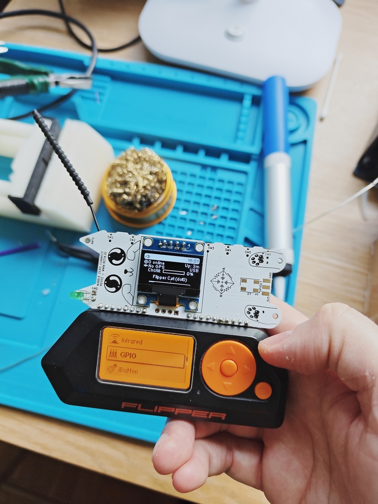
I soldered the included angled headers to the bottom connectors of the Nibble Zero. Plug it in to the Flipper, and that's pretty much it.

Software

In order for the Flipper to power the Nibble, 5V out needs to be activated on the GPIO, this is done through the menus. The display on the Nibble should light up after a few seconds and the Meshtastic logo should show.

If it doesn't there's a web flasher that can flash the correct firmware to it: https://nugget.dev/

The Nibble should now configured to forward serial data to it's GPIOs so the Flipper can communicate with it. The following settings should be set:

Setting | Value |–|–| Serial | enabled Echo | enabled RX | 44 TX | 43 Baudrate | 115200 Serial mode | PROTO

The ZeroMesh app

The easies way install the app (as of today) is to clone the repository and built it with ufbt. ufbt is Flipper Zeros own app builder, install it with pip: pip install ufbt

git clone https://github.com/SAMS0N1TE/ZeroMesh.git cd ZeroMesh
ufbt build 19:15:04.225 [I] Deploying SDK for f7 19:15:04.225 [I] Fetching version info for UpdateChannel.RELEASE from https://update.flipperzero.one/firmware/directory.json 19:15:04.629 [I] Using version: 1.4.3 19:15:04.629 [I] uFBT SDK dir: /home/isac/.ufbt/current 19:15:05.266 [I] Deploying SDK 19:15:05.514 [I] SDK deployed. scons: Entering directory /home/isac/.ufbt/current/scripts/ufbt' APPCHK /home/isac/.ufbt/build/zeromesh.fap Target: 7, API: 87.1

The app file is now available in ~/.ufbt/build. I proceeded to install the app using qFlipper by just dragging and dropping the .fap file in the file explorer.

Trying it out

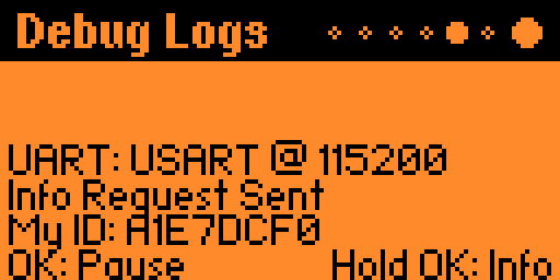
After all the preparation all should be set to just try it out. I doulbe checked the debug logs in the app to double check the connection with the Flipper Zero. Everything looked good.

debug log

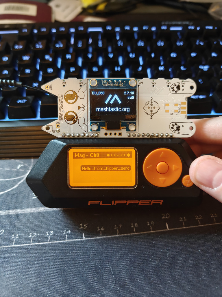
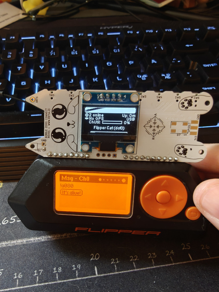
I realized just after the fact that I needed to long press on the underscore to write spaces on the Flipper keyboard. But I was able to send a message to the local public channel (which is shown as Ch0 in the app)

message sent

And from my other node I could see it:

received message

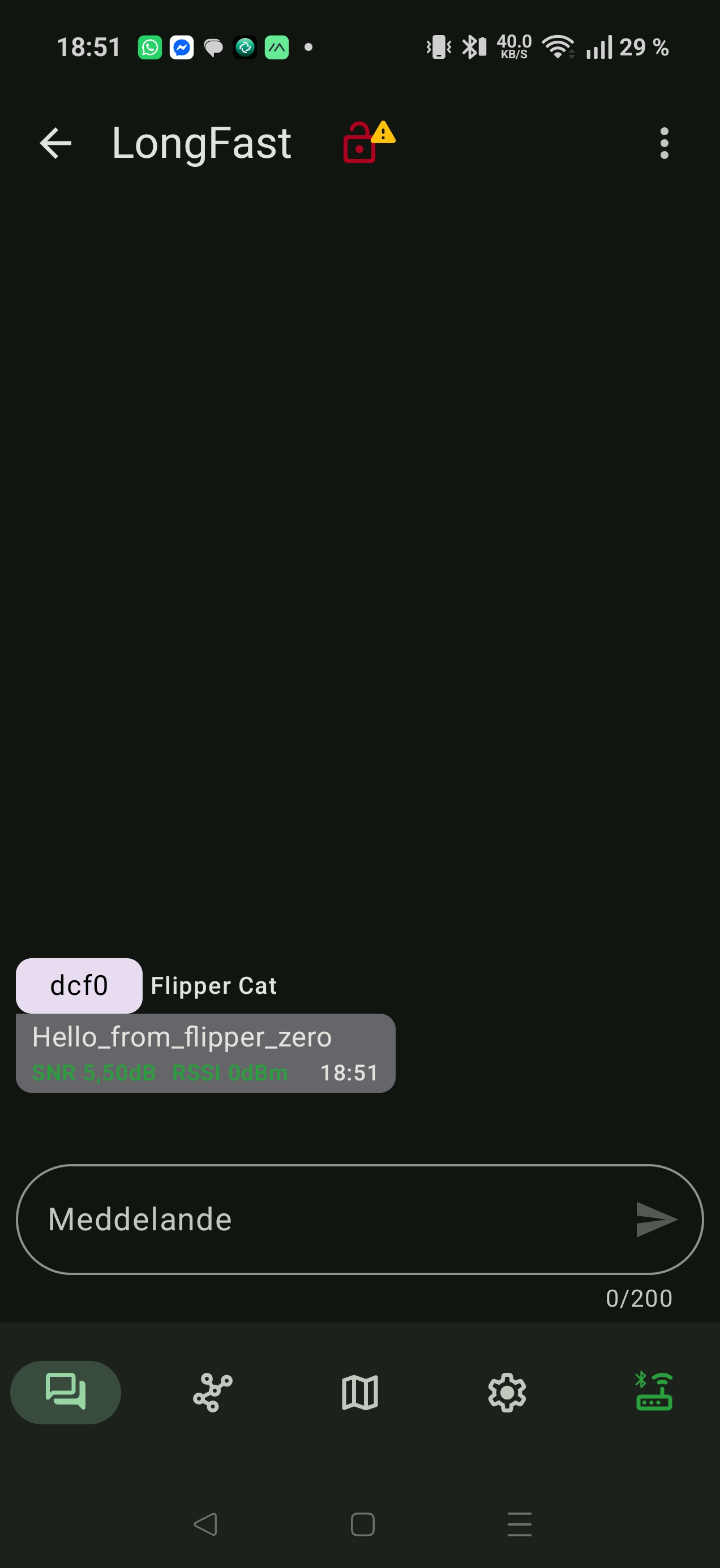
And my reply from my other node: reply received

Conclusion

The Nibble Zero is an interesting module for those who has a Flipper Zero and want to use it as a mesh network. The apps that are available are pretty basic, but they work. Using Meshtastic on the flipper zero is a great way to use your hardware for something other than just debugging, since it now actually has a great way of communuication to it. Integrating the Nibble Zero with other functions of Flipper i.e. sending scanned NCF data to another Flipper using the Nibble Zero could be an interesting way to share data. (And maybe a future project?) It's worth noting that the version of meshtatic is a slightly modified version of Meshtastic and it's slightly older than the official one.

There are some 3D printable enclosure avaiable here:

https://www.printables.com/model/1544450-nibble-zero-retia-case

https://www.printables.com/model/1561324-nibble-zero-case

Recovering a bricked Wismesh Repeater with a Black Magic probe

I got my hands on a Wishmesh Repeater that got bricked during an update. But after opening it I saw that there actually was an SWD header and after some googling around I found out that I could use a BMP to reflash the bootloader to unbrick the Repeater.

So I got myself a BlackPill F411CE.

So I opened up the Repeater to solder on a pin header, but had to lift the supercap shown in the picture below. It was glued to the board so I had to carefully cut it free to I could tilt it up and solder on the header.

Backside with supercap

And now the header is soldered on SWD header on

Now I need to make my own Black Magic Probe. I downloaded the repo: git clone https://codeberg.org/blackmagic-debug/blackmagic.git

there are some submodule issues since it was recently moved to codeberg so I manually cloned it:

cd blackmagic/deps rm -rf libopencm3 git clone https://codeberg.org/blackmagic-debug/libopencm3.git

Now lets build the code: meson setup build —cross-file=cross-file/blackpill-f411ce.ini -Dbmd_bootloader=true meson compile -C build`

Now we've built the bootloader and the BMP firmware, time to flash my BlackPill F411CE.

Connect a usb cable to the PC to power it.

I actually used an ST-link and STM32CubeProgrammer and flashed the bootloader to 0x08000000 and the BMP firmware to 0x08004000 after a full chip erase.

Confirm that the BMP is now working, on linux run: lsusb And look for something like this: Bus 001 Device 034: ID 1d50:6018 OpenMoko, Inc. Black Magic Debug Probe (Application)

Now connect your new BMP to the repeater SWD port:

Wismesh Repeater Blackpill BMP
3V3 Any 3V3
GND Any GND
SWDIO PB9(B9)
SWCLK PB8(B8)
NRST PA5(A5)

Programming

And now it's time to flash the bootloader. Download the Wismesh bootloader .hex file from https://github.com/oltaco/WisCore_RAK4631_Bootloader/releases

Now it's time to load up gdb: arm-none-eabi-gdb target extended-remote /dev/ttyACM0 monitor swd_scan

You should get something like: nrf52840 M4 and mrf52840 Access Port You would go for the first.

Contact!

attach 1 monitor erase_mass load /path/to/WisCore_bootloader.hex monitor reset detach quit

Now unplug the power to the repeater by pulling out the 3v3 and wait ~10 seconds. Connect a usb cable and double press the button and it should now enter DFU mode. Now you can flash the meshtastic firmware.

Congrats! You've unbricked your repeater with a cheap diy debug probe!

I realized after looking into the build guides on OTland that the build guide for Ubuntu were lacking and the code base were actually incompatible with modern distros since it's using deprecated boost libraries. So I took some time to figure out what I needed to do to fix it.

Follow the guide on: https://docs.otland.net/ots-guide/running-your-first-linux-web-and-otserver

But install these additional packages

liblua5.4-dev libboost-locale-dev libboost-json-dev

remove “system” from line 103 in CMakeLists.txt in project root remove “Boost::system” from line 168 in src/CMakeLists.txt

Now you can proceed with the rest of the setup

Background

About ten years back I bought a Velleman K7203 as a fun soldering project, and to use as a power supply for a future project.

This will provide a very stable output voltage with <0.5 mV ripple which is pretty nice.

And now, 10 years later, it's time for that future project.

Assembly

The most important thing that was required for PSU after the module itself was a transformer, and preferably toroidal transformer. And those things are not cheap, unless you're lucky and find one second hand.

I got a 230VAC/25VAC 2A transformer that I'm gonna use. And together with that I got a metal enclosure from AliExpress.

I began with drilling holes in the front for the banana plug connectors, and followed the standard pitch of 0.75” between the connectors.

Front inside

And from the front it will look like this: Front outside

After drilling some holes and mounting the power supply and the transformer with some spacers and mounting hardware it looks like this:

Inside complete

I made sure to use a ground cable since I use a metal enclosure, and I also use a C14 connector with a power switch and a fuse as recommended by the PSU manufacturer.

Testing

The PSU in an assembled state is very plain, and it gives a voltage range between 2 to 17.9 V.

Inside complete

Next steps

For now the voltage adjustment is located on the PSU, so one would need to open the case to adjust it. In the future I'd like to have a potentiometer mounted on the front together with a VA meter. And that will be for a future blog post.

The AST Advantage 611s, the first computer my family got. With a whopping 8MB of RAM and an IBM 5x86 CPU clocked at 100MHz.

We recently managed to get it working again, and came to the conclusion that it would be a good idea to make a backup of the BIOS on the motherboard, since there may not exist too many backups out there.

I ordered a XGecu T48 Universal Programmer with the appropriate adapters for the flash chip for 59$ If you want to check it out you can find it here: https://xgecu.myshopify.com/products/xgecu-new-t48-tl866-3g-programmer-support-28000-ics-for-spi-nor-nand-flash-emmc-bga-tsop-sop-plcc-9-parts

The T48 is also called TL866-3G and is of course the successor to the popular TL866 universal programmer.

Removing the chip and identifying the model number

Taking a look in the computer, the BIOS flash is located in the PLCC44 socket, but it's a bit hard to reach so the ISA riser card needs to be removed.

Flash Chip location

A closer look at the chip shows a sticker and a serial number that points back to 94.

Flash Chip sticker

Removing the chip was easy because of the included chip removal tool. Just place the hooks in the slots in the corners and press until it pops out.

Flash Chip removal

Now I needed to find out what type of flash chip it really was. But I'd rather not ruin the sticker. So I used a scalpel blade to carefully remove the sticker so I could read the model number. (Pardon for the out of focus photo)

The flash chip model number

A quick google search told me that it was an Intel N28F001BX-T150 1Mbit (128KB) Boot block flash memory.

Reading the flash using Xgpro

(Sadly during the migration to another server, the pictures where lost in this part)

IC flashing

The program used for the T48 is the Xgpro. The first thing I did was to make sure the right IC was selected by clicking “Select IC” in the upper left corner.

IC selection

After marking the correct IC and clicking “Select” I clicked on “READ” in the upper toolbar. Now a new window appeared with a picture on how to seat the chip in the adapter and the ZIF socket. After connecting it according to the picture I clicked “Read” and the “BACK”

Read data

Now I could see the data from the chip. Scrolling down a bit, I could find some readable text like a Copyright from 1984 and an AST Research Copyright from 1995. Cool!

Flash dump

After confirming that I got some data from the chip I saved it to a .bin file using the “SAVE” button on the top left.

Save dialog

My plan is to upload the bin file to a site like The Retro Web, this page in particular: https://theretroweb.com/motherboards/s/ast-advantage!-610-611-486-202728-101 So people can find a copy of the BIOS and easily flash a new one if they ever need to do that.